E-mail : inquiry@ronsteel.comPhone : +8615308477503

We are committed to providing one-stop service for steel pipe products to customers around the world.

ASTM A511 tubes shall be made by a seamless process and by either cold working or hot working as specified. It is usually manufactured by hot-working steel and then cold finishing the hot-worked tubing to produce the desired shape, dimensions, and properties All austenitic tubes shall be furnished in the annealed condition.
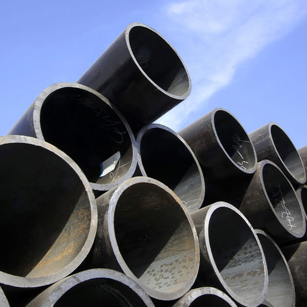
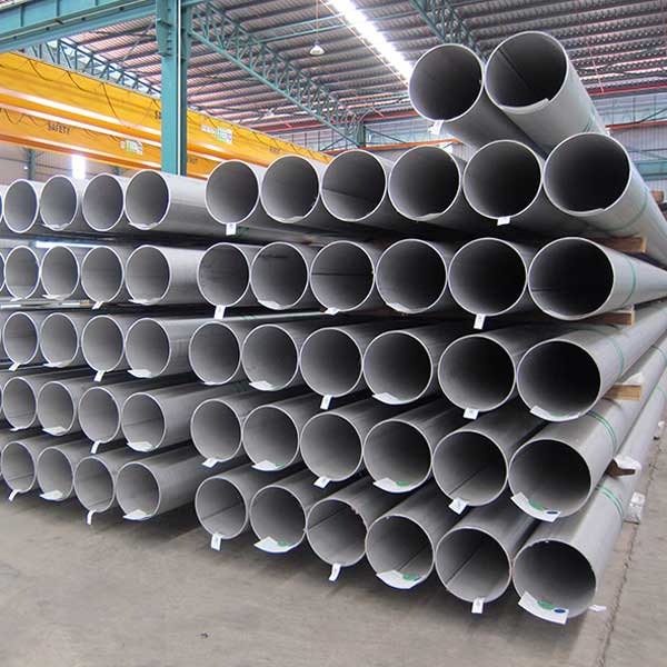
ASTM A511 Stainless Steel Mechanical Tube
ASTM A511 covers seamless stainless steel tubes for use in mechanical applications.
Application: Mechanical applications where corrosion-resistant or high-temperature strength is needed.
Austenitic stainless steel grades:304,304L, 304H, 316, 316L, 316Ti, 316H, 321, 321H, 317, 317L, 347, 347H, 310, 310S, 310H
Outer Diameter:ranging from¼”to 12 3/4”
Wall Thickness: 0.02”to 1”(0.5 mm to 25.4 mm)
ASTM A511 Chemical Composition:
|
Grade |
Carbon |
Mn |
P |
S |
Si, max |
Ni |
Cr |
Mo |
Ti |
Columbium plus Tantalum |
Se |
|
|
|
max |
max |
max |
|
|
|
|
|
|
|
|
MT 302 |
0.08 to 0.20 |
2 |
0.04 |
0.03 |
1 |
8.0–10.0 |
17.0–19.0 |
... |
... |
... |
... |
|
MT 303 |
0.15 max |
2 |
0.2 |
0.15 min |
1 |
8.0–10.0 |
17.0–19.0 |
... |
... |
... |
... |
|
MT 303Se |
0.15 max |
2 |
0.04 |
0.04 |
1 |
8.0–11.0 |
17.0–19.0 |
... |
... |
... |
0.12–0.2 |
|
MT 304 |
0.08 max |
2 |
0.04 |
0.03 |
1 |
8.0–11.0 |
18.0–20.0 |
... |
... |
... |
... |
|
MT 304L |
0.035 maxA |
2 |
0.04 |
0.03 |
1 |
8.0–13.0 |
18.0–20.0 |
... |
... |
... |
... |
|
MT 305 |
0.12 |
2 |
0.04 |
0.03 |
1 |
10.0–13.0 |
17.0–19.0 |
... |
... |
... |
... |
|
MT 309S |
0.08 max |
2 |
0.04 |
0.03 |
1 |
12.0–15.0 |
22.0–24.0 |
... |
... |
... |
... |
|
MT 310S |
0.08 max |
2 |
0.04 |
0.03 |
1 |
19.0–22.0 |
24.0–26.0 |
... |
... |
... |
... |
|
MT 316 |
0.08 max |
2 |
0.04 |
0.03 |
1 |
11.0–14.0 |
16.0–18.0 |
2.0–3.0 |
... |
... |
... |
|
MT 316L |
0.035 maxA |
2 |
0.04 |
0.03 |
1 |
10.0–15.0 |
16.0–18.0 |
2.0–3.0 |
... |
... |
... |
|
MT 317 |
0.08 max |
2 |
0.04 |
0.03 |
1 |
11.0–14.0 |
18.0–20.0 |
3.0–4.0 |
... |
... |
... |
|
MT 321 |
0.08 max |
2 |
0.04 |
0.03 |
1 |
9.0–13.0 |
17.0–20.0 |
... |
B |
... |
... |
|
MT 347 |
0.08 max |
2 |
0.04 |
0.03 |
1 |
9.0–13.0 |
17.0–20.0 |
... |
... |
C |
... |
A For small diameter or thin wall tubing or both, where many drawing passes are required, a maximum of 0.040 % carbon is necessary in grades MT-304L and MT-316L. Small outside diameter tubes are defined as those under a 0.500 in. [12.7 mm] outside diameter and light-wall tubes as those under a 0.049 in. [1.2 mm] average wall thickness (0.044 in. [1.1 mm] min wall thickness).
B The titanium content shall be not less than five times the carbon content and not more than 0.60 %.
C The columbium plus tantalum content shall be not less than ten times the carbon content and not more than 1.00 %.
Permissible Variations in Outside Diameter, Ovality, Wall Thickness, and Cut-Length Variations
(Cold-Finished Round Tubing)A
|
Outside |
Outside Diameter, Tolerance,B |
Ovality,B Double |
Wall Thickness |
Permissible Variations |
||
|
|
|
|
Over |
Under |
Over |
Under |
|
Under 1⁄2 |
0.005 |
less than 0.015 in. |
15 |
15 |
1⁄8 |
0 |
|
1⁄2 to 11⁄2 , excl |
0.005 |
less than 0.065 in. |
10 |
10 |
1⁄8 |
0 |
|
11⁄2 to 31⁄2 , excl |
0.01 |
less than 0.095 in. |
10 |
10 |
3⁄16 |
0 |
|
31⁄2 to 51⁄2 , excl |
0.015 |
less than 0.150 in. |
10 |
10 |
3⁄16 |
0 |
|
51⁄2 to 8, exc |
0.03 |
less than 0.240 in. |
10 |
10 |
3⁄16 |
0 |
|
8 to 85⁄8 , excl |
0.045 |
less than 0.300 in. |
10 |
10 |
3⁄16 |
0 |
|
85⁄8 to 123⁄4 , incl |
0.062 |
less than 0.350 in. |
10 |
10 |
3⁄16 |
0 |
Permissible Variations in Outside Diameter, Wall Thickness, and Cut-Length Variations
(Hot-Finished Round Tubing)
|
Specified Size, Outside |
Ratio of Wall |
Outside Diameter and Wall Thickness Tolerances |
Permissible Variations |
||||||||||
|
|
|
Wall Thickness, % |
|
||||||||||
|
|
|
Outside |
0.109 in. |
0.109 to |
Over 0.172 to |
Over 0.203 in. |
|
||||||
|
|
|
over |
under |
over |
under |
over |
under |
over |
under |
over |
under |
|
|
|
Under 3 |
all wall thicknesses |
0.023 |
0.023 |
16.5 |
15 |
15 |
15 |
14 |
14 |
12.5 |
12.5 |
3⁄16 |
0 |
|
3 to 51⁄2 , excl |
all wall thicknesses |
0.031 |
0.031 |
16.5 |
15 |
15 |
15 |
14 |
14 |
12.5 |
12.5 |
3⁄16 |
0 |
|
51⁄2 to 8, excl |
all wall thicknesses |
0.047 |
0.047 |
… |
… |
… |
… |
14 |
14 |
12.5 |
12.5 |
3⁄16 |
0 |
|
8 to 103⁄4 , excl |
5 % and over |
0.047 |
0.047 |
… |
… |
… |
… |
… |
… |
12.5 |
12.5 |
3⁄16 |
0 |
|
103⁄4 to 123⁄4 , incl |
under 5 % |
0.063 |
0.063 |
… |
… |
… |
… |
… |
… |
12.5 |
12.5 |
3⁄16 |
0 |
A These tolerances apply to cut lengths up to and including 24 ft (7.3 m). For lengths over 24 ft, an additional over tolerance of 1⁄8 in. (3.1 mm) for each 10 ft (3 m) or faction thereof shall be permissible, up to a maximum tolerance of 1⁄2 in. (12.7 mm).
Straightness Tolerances (Cold-/Finished or Hot-/Finished Round Tubing)
|
Size Limits |
Max Curvature |
Max Curvature in Total Lengths, in. |
Max Curvature for |
|
OD 5 in. and smaller. Wall thickness, over 3 % of OD but not over 0.5 in. |
0.03 |
0.030 3 [(Number of feet of length)/3] |
Ratio of 0.010 in./ft |
|
OD over 5 in. to 8 in., incl. Wall thickness, over 4 % of OD but not over 0.75in. |
0.045 |
0.045 3 [(Number of feet of length)/3] |
Ratio of 0.015 in./ft |
|
OD over 8 in. to 123⁄4 , incl. Wall thickness, over 4 % of OD but not over 1 in. |
0.06 |
0.060 3 [(Number of feet of length)/3] |
Ratio of 0.020 in./ft |
A The usual procedure for measuring straightness is by means of a 3-ft (0.9 m) straight edge and feeler gage. If determined by the dial indicator method, the values obtained will be approximately twice those determined by the straightedge feeler gage method.


